Design Guide for bus bars
Basics and Electrical Parameters
-
Design Guide Basics
Design guides for bus bars
Conductors
Conductor material selection is critical in meeting electrical performance and mechanical rigidity requirements. Common materials used are copper, aluminum, and a variety of copper alloys. The material chosen, the mechanical constraints and the electrical performance for the specific application determine the conductor’s minimum mechanical dimensions (see Conductor Size in the Electrical Design section).
Thermal considerations may require system ventilation to remove excess heat from the bus bar. In this case, bus bar configuration might be low in profile, thereby changing the orientation of the bus structure and the airflow. Bus bars may also serve to remove heat from components by performing as a heat sink.
The selection of tabs or terminations may determine conductor thickness if there’s a need to accept studs, nuts, tabs or threaded inserts. Minimum mechanical requirements for the connection style chosen must be considered for overall efficiency and cost effectiveness.
Grounds
The ground return conductor should be equal in size and circular mil area to its corresponding voltage conductor. A few advantages of a separate ground return are:
- double the effective capacitance;
- greater area for cooling, to minimize the voltage drop due to temperature rise;
- drastically reduced intercoupling effects and
- the opportunity for advantageous shielding between levels, obtained by the use of interleaved grounds.
Mounting
To mount a bus bar to an assembly structure, hardware (studs, holes, etc.) can be manufactured into the conductors. An alternative ground plane may be added as support for the bus bar assembly and to provide a platform for mounting hardware.
Finish
Mersen offers in-house conductor plating in tin, tin-lead, nickel, silver, or gold. Plating is a major consideration in designing a bus bar because it is the point of contact for all bus bar electrical connections. The plating can provide advantageous electrical properties, decreasing the voltage drop. When gold is used, it is generally only plated on termination surfaces to minimize cost.
Insulation
Bus bars use many different types of adhesive-coated insulation materials to permit structure layers to be laminated together. There are added benefits from an electrical perspective. Insulation provides an inside and outside barrier to its installed environment. Insulations can increase the capacitance and lower the inductance and impedance. Commonly used insulation materials are: Nomex®, Tedlar®, Mylar®, Kapton®, Ultem®, Mylar/Tedlar, Tedlar/Mylar/Tedlar, Valox®, epoxy-glass, heat shrink tubing, and epoxy powder coating. There are many different thicknesses of these insulation materials available. Contact a Mersen engineer for more information. Special insulations are available upon request.
Cost considerations
Prices of bus bar assemblies vary depending upon quantity ordered. In addition, individual dimensional characteristics, materials, manufacturing techniques, the interconnection scheme, plating finish, insulation, and hardware requirements affect overall cost.
Mersen engineers are available to assist in developing the most efficient and cost-effective design to provide solutions to any power distribution problem. The earlier we are involved in your design process, the more cost-effective your solution is likely to be. Early involvement enables us to optimize both ease of manufacturing and turnaround time. We recommend that you contact a new-product development engineer before you start designing your laminated bus bar power distribution system.
Electrical design
Important characteristics of laminated bus bars are resistance, series inductance, and capacitance. As performance parameters of electronic equipment and components become more stringent, these characteristics take on even more importance. In determining the impedance of a power distribution system, these characteristics are significant in solving two of the most important problems for designers – resistance and noise. It is important, therefore, to understand the electrical characteristics of the laminated bus bar.
-
Contact us
The right design for your application
-
Design Guide Formulas
Electrical parameters
Conductor Size
Calculating conductor size is very important to the electrical and mechanical properties of a bus bar. Electrical current-carrying requirements determine the minimum width and thickness of the conductors. Mechanical considerations include rigidity, mounting holes, connections and other subsystem elements. The width of the conductor should be at least three times the thickness of the conductor.
Additions of tabs and mounting holes change the cross-sectional area of the conductor, creating potential hot spots on the bus bar. The maximum current for each tab or termination must be considered to avoid hot spots.
Cross-sectional area and the length determine bus bar conductor size. Cross-sectional area (..4) is equal to conductor thickness (t) multiplied by conductor width (w).
A value of approximately 400 circular mils per ampere is a traditional basis for design of single conductors. Since bus bars are not round, circular mils must be converted to mils squared (simply multiply the circular mils value by 0.785).
-
The following formula determines the minimum cross-sectional area of a conductor. This area should be increased by five percent for each additional conductor laminated into the bus structure. This extra five percent is a safety factor compensating for the compounding heat gain within the conductors.
This equation calculates the minimum cross-sectional area necessary for current flow:
A= 400(I)(0.785)(1+.05(N-1)](1*10-6)inches2
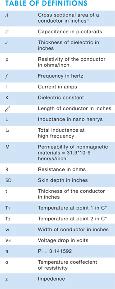
A = Cross-sectional area of the conductor in inches²
l = Max DC current in amperes
N = Number of conductors in the bus assemblyTo calculate the cross-sectional area of an AC current source, you must take frequency into consideration (See the section on Skin Effect).
Note: This formula has a breakdown point at approximately 300 amps of current. For calculations involving larger currents, we suggest you contact a Mersen engineer and refer to the ampacity table. In addition, you can find ampacity charts and comparative graphs at the Copper Development Association’s website, copper.org.
-
Capacitance
Capacitance of the bus arrangement depends upon the dielectric material and physical dimensions of the system. Capacitance varies only slightly with frequency change, depending on the stability of the dielectric constant. This variation is negligible and therefore is omitted in this analysis:
C=0.225(K)(w)(l)
–––––––––––––– picofarads
(d)Increased capacitance results in a decreasing characteristic impedance. Low impedance means greater effective signal suppression and noise elimination. It is therefore desirable to develop maximum capacitance between conductor levels. This may be achieved by:
- keeping the dielectric as thin as possible, consistent with good manufacturing and design practices.
- using dielectrics having a high relative permitivity (k factor)
-
Skin effect
Because of skin effect phenomena, inductance and resistance are dependent on frequency. At high frequency, currents tend to flow only on the surface of the conductor. Therefore the depth of penetration of the electromagnetic energy determines the effective conducting volume. The skin depth is given by:

-
For copper:
As frequency increases, inductance decreases to a limiting value, whereas the resistance increases indefinitely as the frequency approaches infinity.

-
Inductance
Maintaining a low inductance results in a low characteristic impedance and greater noise attenuation. When minimum inductance is a design objective, consider these tips:
- Maxomize the dielectric thickness
- Maximize the conductor width
- Increase the frequency
There are two types of inductance to be determined: internal inductance, which is a result of flux linkages within a conductor, and external inductance, which is determined by the orientation of the two current carrying conductors.
Distribution of current throughout a conductor at high frequencies is concentrated near the surfaces (called the “skin effect”). The internal flux is reduced and it is usually sufficient to consider only the external inductance. At low frequencies, however, the internal inductance may become an appreciable part of the total inductance. The formula for calculating the internal inductance at a low frequency is extremely lengthy and thus omitted in this analysis.
-
The formula for external inductance is:

-
High-Frequency Inductance (t>SD)

-
Resistance
To calculate the DC conductor resistance, the following formula applies (Resistance at 20°C):

-
To determine DC conductor resistance at temperatures above 20°C, use this formula:

-
For high frequencies the skin depth is taken into consideration. The formula for AC resistance is:
For (t >2SD)
-
AC resistance at 20 degrees C

-
Voltage drop
As current travels across a conductor, it loses voltage. This is caused by the resistivity of the conductor. The losses are referred to as voltage drop. Use this formula to calculate the voltage drop across the conductors:

-
Impedance
In the design of laminated bus bars, you should consider maintaining the impedance at the lowest possible level. This will reduce the transmission of all forms of EMI (electromagnetic interference) to the load.
Increasing capacitance and reducing inductance are the determining factors in eliminating noise. The formula for calculating characteristic impedance is: